Braking Resistors in VFD Systems: How to Control Regenerative Energy for High-Inertia Loads
Introduction
VFD braking resistors are critical for protecting variable frequency drives (VFDs) from overvoltage, especially when controlling high-inertia loads like induced draft fans. Without proper braking, regenerative energy from deceleration can damage components and cause costly downtime. This guide explains how braking resistors work, why they are essential, and how to apply them effectively.
How a Three-Phase Induction Motor Adjusts Speed
A three-phase AC supply generates a rotating magnetic field, which cuts through the rotor conductors, inducing current. The interaction between this rotor current and the stator field creates torque, rotating the motor.
Synchronous speed: n0=60f/pn_0 = 60f / p
Slip: s=(n0−n)/n0s = (n_0 – n) / n_0
Motor speed: n=60f/p(1−s)n = 60f/p (1 – s)
Since pole count and slip are fixed after manufacturing, changing motor speed in practice means changing the supply frequency—this is the role of the VFD.
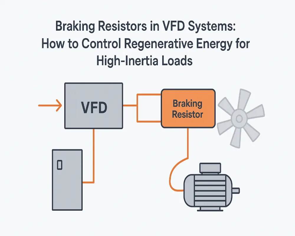
Structure and Working Principle of VFDs
A VFD consists of two main circuits:
Main power circuit – Includes the rectifier (AC to DC), filter, and inverter (DC to adjustable AC).
Control circuit – Processes feedback and sends control signals to the main circuit.
During operation, energy from high-inertia loads can flow back to the DC bus when the motor decelerates, raising the voltage dangerously.
Why Regenerative Energy Becomes a Problem
When a high-inertia load keeps spinning faster than the synchronous speed during deceleration, the motor acts as a generator. This regenerative energy cannot be fed back into the grid in most systems, so it accumulates in the DC bus, causing overvoltage. If unaddressed, the VFD will trip to protect itself, stopping production unexpectedly.
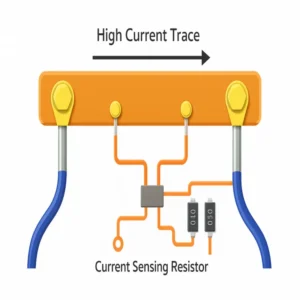
The Role of Braking Resistors
Braking resistors convert regenerative energy into heat, preventing DC bus overvoltage. They work with a braking unit, which detects when the bus voltage exceeds a set threshold and switches the resistor into the circuit. Once the voltage drops, the resistor disconnects automatically.
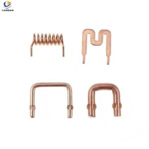
Internal braking resistors – For small VFDs, space-limited applications.
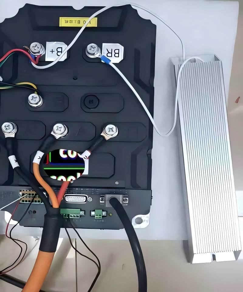
External braking resistors – For large VFDs or heavy-duty braking needs.
Real-World Example: Solving Frequent Overvoltage Trips
At a coal chemical plant, two 18.5 kW induced draft fans experienced frequent VFD overvoltage trips during rapid speed changes. Installing external braking resistors eliminated downtime by safely dissipating excess energy, ensuring stable production.
Key Takeaways
Identify load type – High-inertia loads require external braking resistors.
Match resistor specs – Consider resistance value, power rating, and thermal capacity.
Monitor results – Ensure braking cycles do not exceed resistor capacity.