Shunt Resistor Based Current Sensing: Circuit Design, Error Analysis, and Practical Selection Tips
Introduction
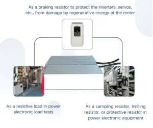
Accurate current measurement is a fundamental requirement in modern power electronics systems, including motor drives, power supplies, battery management systems, inverters, and industrial automation equipment.
Since microcontrollers and digital processors cannot directly process current signals, the current must first be converted into a proportional voltage signal and then sampled by an analog-to-digital converter (ADC). Among various current sensing technologies, shunt resistor–based current sensing remains one of the most widely used methods due to its low cost, high accuracy, and wide current measurement range.
This guide focuses on practical engineering considerations, including working principles, circuit configurations, error sources, layout techniques, and thermal design trade-offs commonly encountered in industrial shunt-based current sensing applications.
1. Principle of Shunt Resistor Current Sensing
The basic principle of shunt resistor current sensing is based on Ohm’s law:
V = I × R
By inserting a low-value resistor into the current path, the flowing current generates a small voltage drop across the resistor. This voltage is proportional to the current and can be amplified using an operational amplifier or a dedicated current-sense amplifier before being processed by the ADC.
Shunt resistors are typically low-ohmic components, ranging from several milliohms down to micro-ohms, in order to minimize power loss while maintaining sufficient measurement resolution.
Advantages and Limitations
Advantages
Low cost and simple implementation
High measurement accuracy
Suitable for both DC and AC current measurement
Wide measurable current range
Limitations
Introducing a shunt resistor into the current path causes additional power dissipation according to:
P = I² × R
As current increases, power loss and self-heating become significant, making shunt-based sensing less suitable for very high-current applications without proper thermal design.
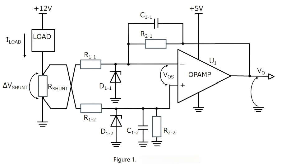
2. Typical Circuit Configurations
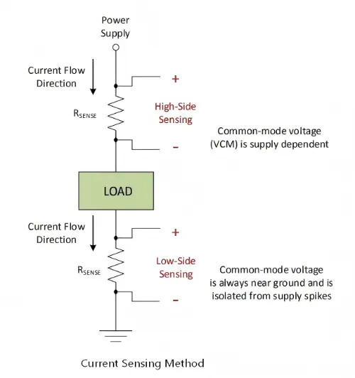
Depending on the placement of the shunt resistor in the circuit, current sensing can be classified into low-side sensing and high-side sensing.
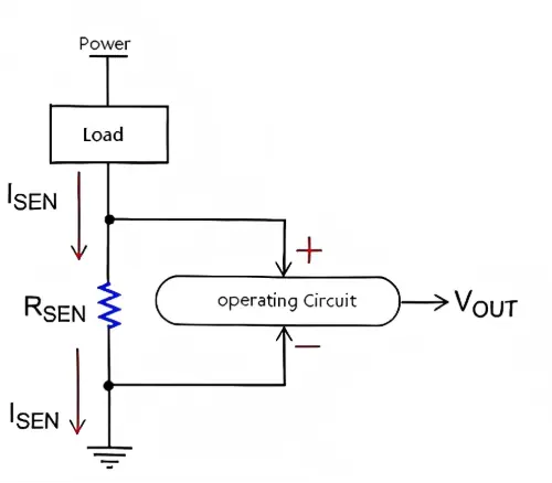
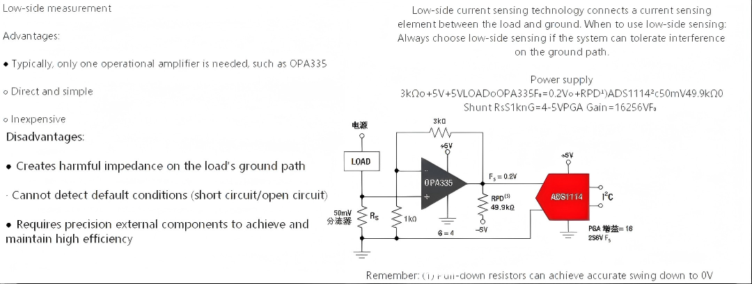
2.1 Low-Side Current Sensing
In low-side sensing, the shunt resistor is placed between the load and system ground.
Low-side sensing is preferred when cost and simplicity are critical and when ground disturbance is acceptable.
Advantages
Low common-mode voltage
Simple amplifier requirements
Easy circuit implementation
Disadvantages
Ground potential shift
Inability to detect load short-to-ground faults
Possible interference with system ground reference
This method is commonly used in industrial and telecom systems with stable ground references.
2.2 High-Side Current Sensing
In high-side sensing, the shunt resistor is placed between the power supply and the load.
High-side sensing is commonly selected in safety-critical or fault-detection applications despite higher circuit complexity.
Advantages
No disturbance to system ground
Ability to detect load short circuits
More accurate load current monitoring
Disadvantages
High common-mode voltage
Requires specialized current-sense amplifiers or isolation
Increased circuit complexity
For high-voltage systems, isolated current sensing amplifiers are often required to tolerate large common-mode voltage variations.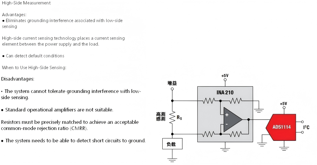
For high-voltage systems, isolated current sensing amplifiers are often required to withstand large common-mode voltage variations.
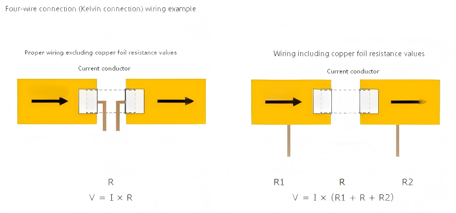
3. PCB Layout and Kelvin Connection
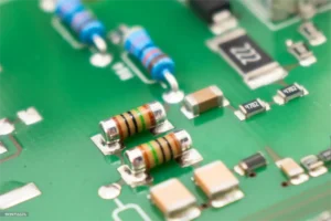
PCB layout is often the largest hidden error source in low-ohmic current sensing.
PCB trace resistance, solder joints, and copper temperature gradients can introduce significant errors, especially when measuring milliohm or sub-milliohm resistance values.
Two-terminal connection includes both solder and PCB trace resistance in the measurement loop
Four-terminal (Kelvin) connection separates current-carrying paths from voltage-sensing paths
Kelvin connection is strongly recommended for high-accuracy current sensing.
Without Kelvin connection, achieving sub-milliohm measurement accuracy is practically impossible.
4. Major Error Sources in Shunt-Based Current Sensing
In practical designs, measurement accuracy is influenced by multiple error sources. Understanding and controlling these factors is essential for achieving stable and reliable current measurement in industrial systems.
4.1 Shunt Resistor Tolerance
The initial resistance tolerance directly defines the baseline measurement accuracy.
Typical tolerance classes include ±1%, ±0.5%, and ±0.1%.
For precision current sensing applications, shunt resistors with tighter tolerance are strongly recommended.
4.2 Temperature Coefficient of Resistance (TCR)
The resistance value varies with temperature according to the temperature coefficient of resistance (TCR), which can introduce measurement drift under operating conditions.
Primary contributors include:
Self-heating caused by I²R power dissipation
Ambient temperature variation
Thermal gradient across the resistor body
Low-TCR alloy materials combined with proper thermal design are essential to minimize temperature-induced error.
4.3 Amplifier Offset and Gain Error
Offset voltage, input bias current, and gain error of the amplifier directly affect output accuracy. These errors become increasingly significant when the shunt voltage is very small.
Careful amplifier selection and proper calibration are required for high-precision measurements.
4.4 Power Dissipation and Thermal Gradient
High current results in significant power dissipation:
P = I² × R
Uneven temperature distribution across the resistor may generate thermal electromotive force (EMF) and additional offset errors, further degrading measurement accuracy.
For a general definition of current shunt measurement, see:
Current sensing – Wikipedia
https://en.wikipedia.org/wiki/Current_sensing
5. How to Select a Shunt Resistor for Your Application
Proper shunt resistor selection is the most critical step in current sensing design.
5.1 Resistance Value Selection
The resistance value should balance:
Sufficient output voltage for ADC resolution
Acceptable power loss
Minimal impact on system efficiency
Typical full-scale shunt voltage ranges from 50 mV to 100 mV.
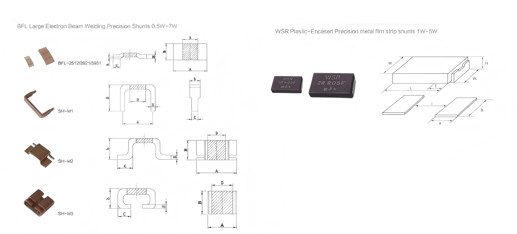
For high-current and precision applications, metal element and metal strip shunt resistors are commonly used due to their low inductance, high power capability, and long-term stability.
5.2 Power Rating and Derating
Designers should always consider:
Continuous current rating
Short-term overload capability
Adequate derating margin
In industrial designs, a derating factor of approximately 50% is commonly applied.
5.3 Accuracy and Long-Term Stability
Key performance indicators include:
Initial tolerance
Load life drift
Thermal stability
Resistance aging behavior
In precision systems, long-term stability is often more critical than initial tolerance.
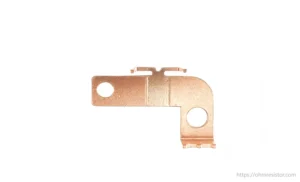
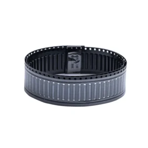
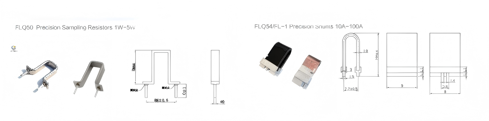
5.4 Package and Construction
Different constructions provide different performance characteristics:
Metal strip shunt resistors
Metal element open-air shunt resistors
Four-terminal Kelvin shunt resistors
Metal strip and metal element constructions offer:
Low inductance
High pulse capability
Excellent thermal performance
These types are widely used in power conversion, motor drive, and inverter systems.
5.5 Environmental Considerations
Designers should evaluate:
Vibration and mechanical stress
Humidity and corrosion
Industrial temperature range
Cooling and airflow conditions
Proper packaging and surface treatment significantly improve long-term reliability.
6. Practical Design Example
Consider a current measurement system with the following requirements:
RMS current: 21 A
Peak current: 30 A
ADC reference voltage: 3 V
Target accuracy: 1%
Assuming a shunt voltage of 150 mV at peak current:
R = 0.15 V / 30 A = 5 mΩ
Power dissipation at RMS current:
P = 21² × 0.005 = 2.205 W
With a derating factor of 2, a 5 W rated shunt resistor is recommended.
This example highlights the importance of evaluating both electrical and thermal limits during shunt resistor selection.
7. Common Design Mistakes and Practical Tips
Common mistakes
Ignoring PCB trace resistance
Not using Kelvin connection
Underestimating self-heating effects
Selecting insufficient power margin
Poor thermal layout
Practical tips
Use four-terminal shunt resistors whenever possible
Place sense traces close to resistor terminals
Provide sufficient copper area for heat dissipation
Keep sense lines away from high-noise switching paths
Conclusion
Shunt resistor–based current sensing remains one of the most cost-effective and accurate solutions for industrial current measurement.
By carefully considering resistance value, power rating, temperature coefficient, layout technique, and long-term stability, designers can achieve highly reliable and accurate current sensing performance.
For high-current and precision applications, selecting the appropriate shunt resistor construction and material is critical to ensuring long-term system reliability.