Surface Mount Conductive Bridge for High-Current PCB Connections
-
20A–30A Current Rating -
Nickel Undercoat + Tin Plating -
EIA Tape & Reel -
High-Conductivity Copper -
PCB Trace Bridging
Description
Surface Mount Conductive Bridge for High-Current PCB Connections
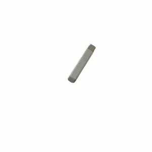
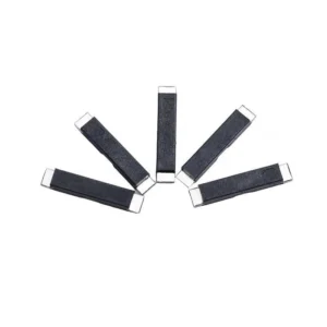
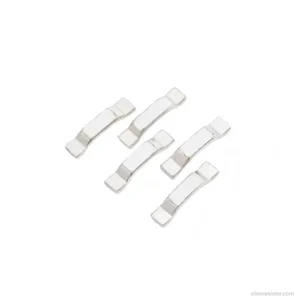
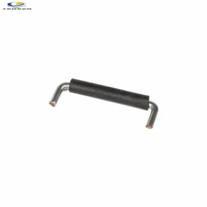
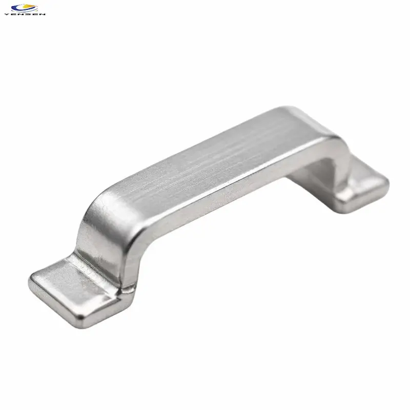
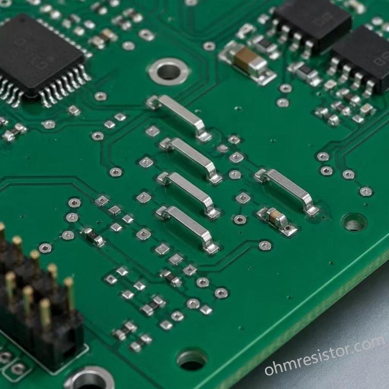
The Surface Mount Conductive Bridge is a compact metal component designed to connect PCB pads and bridge selected circuit paths in space-constrained electronic designs.
Available in H62 brass or high-conductivity copper, depending on the model, it supports PCB power routing and board-level electrical connections. Selected models feature nickel underplating and tin plating for SMT assembly.
With a catalog reference current of 20–30 A, it provides a practical option for compact power PCB designs. The T-C model offers a reference clearance height of 1.8 mm after soldering. Actual current capacity and temperature rise depend on component dimensions, PCB layout, soldering quality, and cooling conditions.
Product Features of Surface Mount Conductive Bridge
- Material Options: H62 brass or high-conductivity copper.
- Surface Plating: Nickel underplating and tin plating on selected models.
- Compact SMT Design: Suitable for surface-mount PCB assembly.
- Board Clearance: 1.8 mm reference clearance height after soldering for the T-C model.
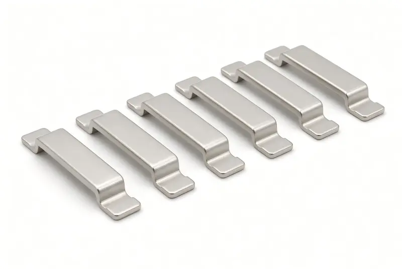
- Packaging: EIA tape-and-reel for compatible models; bulk packaging available.
Technical Specifications
| Parameter | Specification |
|---|---|
| Product Type | PCB Power Trace Jumper |
| Mounting Type | Surface Mount (SMT) |
| Material | H62 Brass / High-Conductivity Copper |
| Reference Current | 20–30 A, catalog reference only |
| Clearance Height | 1.8 mm after soldering, T-C series reference |
| Plating | Nickel Underplating + Tin Plating, depending on model |
| Packaging | EIA Tape & Reel / Bulk |
| Compliance Documents | Confirm availability by model and production batch |
Note: Specifications and options vary by model. Please confirm the applicable drawing and technical requirements before ordering.
Full Model Selection Guide
Select the jumper according to the required span, overall dimensions, board clearance, material, and assembly method.
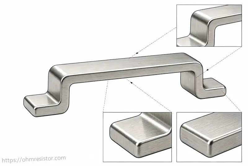
Dimension of Surface Mount Conductive Bridge
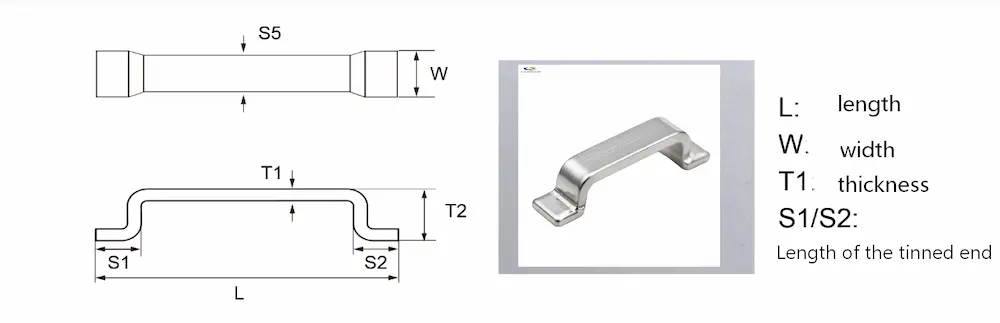
unit: mm |
||||||
| Type | L | W | T1 | T2 | S1/S2 | S5 |
| TFe/TCu-5.2C-OR | 5.2±0.2 | 1.5±0.2 | 0.4±0.15 | 0.6±0.15 | 1.5±0.4 | 1.1±0.3 |
| TFe/TCu-8.2C-0R | 8.2±0.2 | 1.5±0.2 | 0.4±0.15 | 0.6±0.15 | 1.5±0.4 | 1.1±0.3 |
| TCu-10.2C-0R | 10.2±0.2 | 1.5±0.2 | 0.4±0.15 | 0.6±0.15 | 1.5±0.4 | 1.1±0.3 |
| TCu-13.2C-OR | 13.2±0.2 | 1.5±0.2 | 0.4±0.15 | 0.6±0.15 | 1.5±0.4 | 1.1±0.3 |
| TCu-6.4C-0R | 6.4±0.2 | 1±0.2 | 0.5±0.15 | 1.2±0.15 | 1.5±0.4 | 1±0.3 |
For the complete model list, dimensional drawings, and available configurations, please contact us.
Applications
- Power electronics and power conversion PCBs
- High-current PCB connections
- PCB trace bridging and crossover layouts
- Compact power supply assemblies
- Industrial control and motor drive electronics
- Electronic assemblies using automated SMT placement
- PCB power routing, current distribution, industrial electronics, and compact power supply circuits.
Application suitability depends on the specific model, PCB layout, operating conditions, and validation results.
Related PCB Jumper and Busbar Products
Depending on your PCB layout and current requirements, you may also consider our SMD Metal Jumper Bar, SMD Zero Ohm Jumper, and SMD Metal Bridge Jumper.
For higher-current power connections and current distribution, explore our SMD Copper Busbar and High-Current Copper Busbar solutions.
Why Choose us?
- Model-Based Selection: We help match component dimensions and material options to your PCB drawings and application requirements.
- Technical Coordination: We assist with confirming dimensions, plating, packaging, and technical details for application evaluation.
- Export Support: We provide quotation coordination, order communication, quality follow-up, and export documentation for international customers.
Design Considerations
When selecting a surface mount conductive bridge, consider the span, overall length, width, and required board clearance.
For T-C models, the reference clearance height is 1.8 mm after soldering. Check the actual PCB layout, pad positions, underlying traces, and insulation requirements before selection.
Operating current and temperature rise should be verified on the intended PCB assembly and cooling arrangement. For automated SMT production, also confirm the component footprint, pickup area, tape-and-reel orientation, and reflow compatibility.
FAQ
1. What is a Surface Mount Conductive Bridge used for?
It provides a compact conductive connection between designated PCB pads or circuit sections, helping bridge selected PCB routing paths in space-constrained electronic designs.
2. What materials are available?
Depending on the model, material options include H62 brass and high-conductivity copper. Plating options should be confirmed against the applicable product drawing.
3. Can this conductive bridge carry 20–30 A?
The 20–30 A figure is a catalog reference for preliminary selection, not a universal guaranteed rating. Actual current capability depends on component geometry, PCB pads and copper traces, solder joints, operating duration, and cooling conditions. Testing on the intended assembly is recommended.
4. Is tape-and-reel packaging available?
EIA tape-and-reel packaging is available for compatible models intended for automated SMT placement. Bulk packaging may also be available. Please confirm packaging and feeder compatibility for the selected model.
5. Can you provide drawings and compliance documents?
Dimensional drawings and applicable compliance documents can be checked for the selected model and production batch. Please share the required model or application details when requesting a quotation.
Request a Quote
Please provide your required span, overall length, width, clearance height, material preference, operating current, and packaging requirements. If available, include your PCB drawing or footprint.
Contact us to check model availability, technical details, and customization options.