
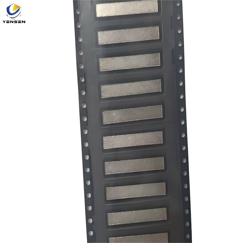

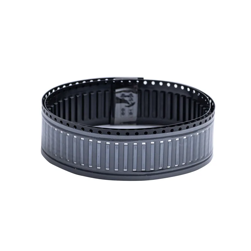
High Current SMD Copper Jumper | Low Resistance PCB Connection Solution
-
Integrated shunt for accurate current sensing
-
High-conductivity copper body
-
Compact and space-saving design
-
Ideal for industrial motor drives and inverters
-
Customizable specs and RoHS compliant
Description
High-Current SMD Copper Jumper for PCB Connections
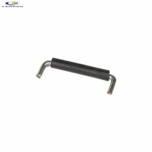
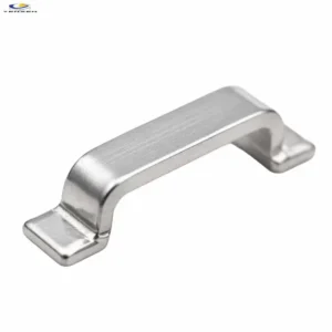
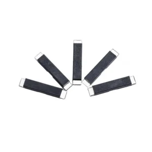
The High-Current SMD Copper Jumper is a surface-mount metal interconnect designed to provide a direct electrical connection between PCB pads. Its compact, flat-bar structure offers an alternative to conventional PCB trace links or chip-style zero-ohm resistors in applications where a metal connection is preferred.
With defined dimensions and customizable design options, this component can be considered for power distribution and other PCB assemblies requiring a compact conductive link. Material, electrical performance, and mounting requirements should be confirmed against the selected specification and application conditions.
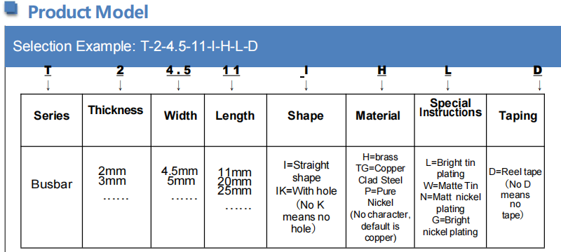
Product Model
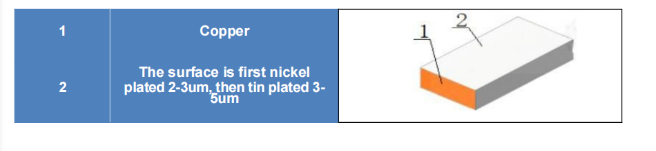
Product Structure
Technical Specifications
| Parameter | Specification |
|---|---|
| Product Type | SMD Copper Jumper |
| Structure | Flat Metal Bar |
| Material | Copper or copper alloy, subject to confirmation |
| Mounting Type | Surface Mount |
| Dimensions | 11 × 4.5 × 2 mm |
| Dimensional Tolerance | Length: ±0.2 mm; Width: ±0.2 mm; Thickness: ±0.05 mm |
| Electrical Resistance | To be confirmed for the selected model |
| Rated Current | Depends on material, dimensions, PCB layout, and thermal conditions |
| Surface Finish | To be confirmed |
| Compliance | RoHS documentation available upon confirmation |
Product Dimensions
Please refer to the product dimension drawing for the physical profile and mounting details. Confirm the dimensions and tolerances against the actual model before PCB layout or production release.Please refer to the product dimension drawing for the physical profile and mounting details. Confirm the dimensions and tolerances against the actual model before PCB layout or production release.
For additional standard sizes and available models, please contact us to request our product catalog.
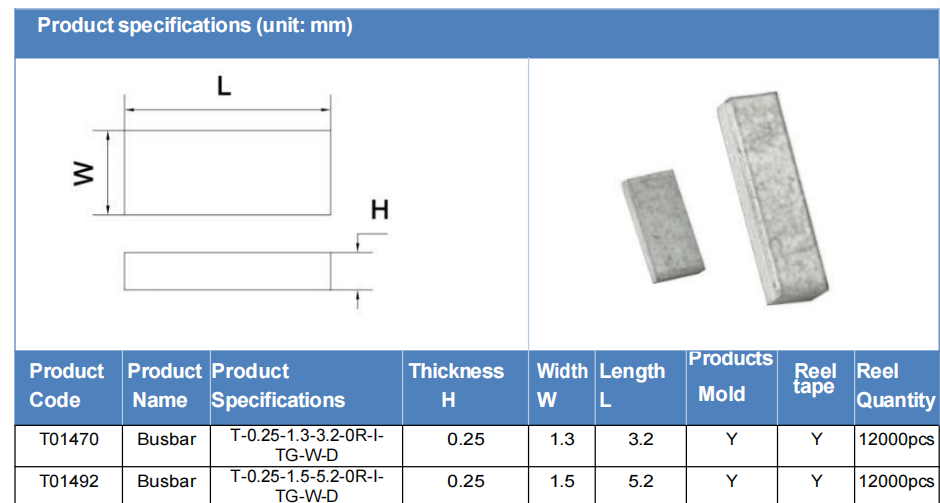
2. Key Features
- Metal Interconnection Structure — Provides a direct conductive link between designated PCB connection points.
- Compact Surface-Mount Design — Supports PCB layouts requiring a low-profile metal interconnect.
- Low-Resistance Connection — A metal connection can offer lower resistance than some conventional chip-style jumper solutions; actual resistance depends on the material and geometry.
- Defined Dimensions — Reference dimensions help engineers assess mechanical fit and PCB layout requirements.
- Customization Options — Dimensions, material, surface finish, and mounting details can be reviewed according to project requirements.
4. Packing & Related Products
Packaging should be selected according to the component design, order quantity, and assembly process.
Please confirm the available packaging format for the selected model, including whether tape-and-reel or other SMT-compatible packaging is required. Packaging details and quantities per pack can be confirmed before ordering.

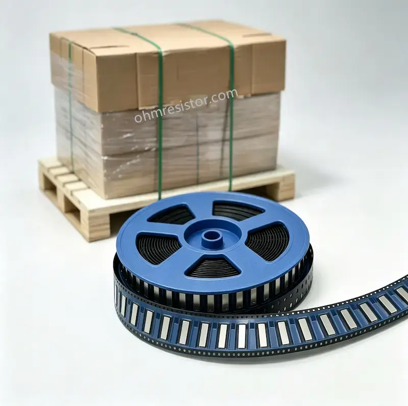
Related Products
If you are comparing different PCB interconnection structures, you may also be interested in:
- Metal Shunt Jumper Bars — Explore other metal jumper bar configurations.
- SMD Zero Ohm Jumper — Review the related product description focused on zero-ohm jumper applications.
5. Applications
The SMD Copper Jumper can be evaluated for applications where a surface-mounted metal connection is suitable, including:
- Power Electronics: PCB power connections and power-module assemblies
- Battery Systems: Selected battery and energy-management PCB connections
- Industrial Electronics: Control boards and power distribution circuits
- Motor Control: PCB interconnections in motor-control equipment
- Custom PCB Assemblies: Projects requiring a compact metal link between designated pads
Suitability depends on the actual electrical, mechanical, thermal, and assembly requirements of each application.
6. FAQ
Q1. What is an SMD copper jumper?
An SMD copper jumper is a surface-mount conductive component used to connect designated PCB pads. Unlike a conventional chip-style zero-ohm resistor, it uses a metal interconnect structure.
Q2. Can this component replace a conventional zero-ohm resistor?
It may be suitable as an alternative in some PCB designs, particularly when a metal interconnect is preferred. Engineers should verify the component dimensions, resistance, current requirements, PCB footprint, and soldering process before making a substitution.
Q3. What is the maximum current rating?
The maximum usable current cannot be determined from the external dimensions alone. It depends on the material, cross-sectional area, contact and solder-joint design, PCB copper, and allowable temperature rise. Please provide your operating current and thermal requirements for evaluation.
Q4. Can the dimensions or material be customized?
Customization may be possible depending on the manufacturing process and project requirements. Please provide a drawing or target dimensions, material requirements, surface finish, and estimated quantity for review.
Q5. Is the component suitable for automated SMT assembly?
The component is intended for surface-mount applications. Compatibility with automated placement and reflow soldering depends on the component design and available packaging format. Confirm the assembly requirements before production.
Q6. Can you provide a drawing or sample?
Please contact us with the target dimensions, application details, and estimated quantity. Drawing availability, sample arrangements, lead time, and supporting documentation can then be confirmed for the selected model.
Need a specification review?
Contact us at lydia@czystech.com with your required dimensions, operating current, PCB application, and estimated order quantity. We can coordinate with our manufacturing partners to review the available options and confirm the relevant technical details before quotation.