SMT vs. THT PCB Jumpers: How to Identify and Use Them in Circuit Design
What Is an SMT PCB Jumper in a Circuit Board?
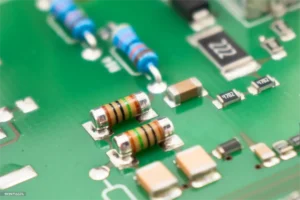
Printed Circuit Boards (PCBs) often need flexible routing solutions. A PCB jumper plays a simple but critical role: it connects two points in a circuit when a direct trace is not possible. Jumpers can take the form of zero-ohm resistors in Surface Mount Technology (SMT) or wires/pins in Through-Hole Technology (THT). Therefore, understanding their function and learning how to distinguish between SMT and THT jumpers is essential for effective PCB design and manufacturing.
How to Quickly Identify SMT vs. THT Jumpers by Appearance
First, consider the placement style. SMT jumpers sit directly on the PCB pads, with no holes required, while THT jumpers pass through holes in the board and are soldered on the opposite side. Additionally, SMT jumpers typically appear smaller and more uniform, whereas THT jumpers often involve discrete wire leads or pin connectors. By observing these characteristics, designers can quickly determine which type of jumper they are dealing with.
Small rectangular shape (looks like a resistor).
Mounted directly on the PCB surface.
Sits flat against copper pads with visible solder at both ends.
Commonly marked as “0Ω” on the silkscreen.
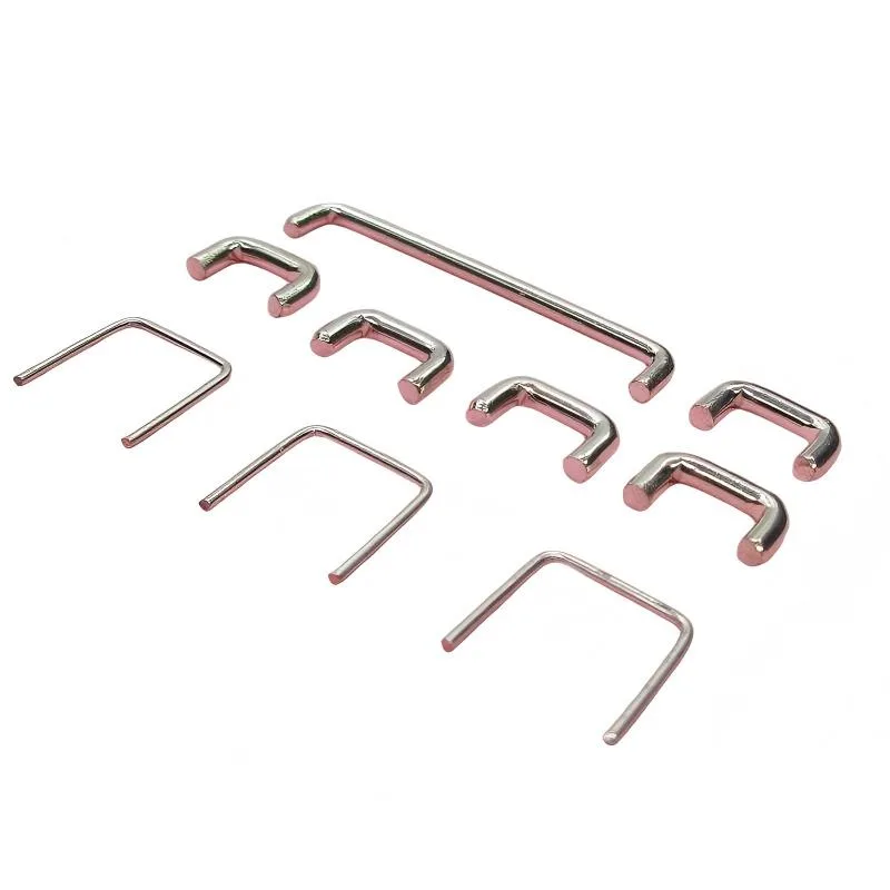
THT (Through-Hole) Jumper
Wire or pin-like component.
Inserted through drilled holes in the PCB.
Visible solder joints on the bottom side.
Often encapsulated with epoxy or insulation.
👉 Quick check: If you see solder pads only on the surface → SMT. If you see drilled holes and legs passing through → THT.
What’s a Surface Mount Jumper?
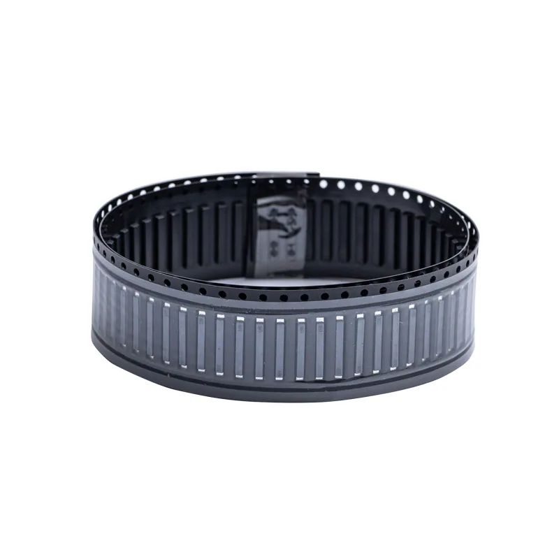
A Surface Mount Jumper (SMT Zero Ohm Resistor) is a resistor-shaped component with near-zero resistance. It is used as a simple connection link but offers advantages in automated assembly because pick-and-place machines handle it like any other SMT resistor.
Benefits of SMT Jumpers:
Easy integration into SMT production lines.
Minimal space usage on the PCB.
Reliable electrical connection with low resistance.
Cost-effective alternative to manual wire jumpers.
Using SMT Jumpers in PCB Design
Routing Flexibility: Allow signal redirection across layers without redesign.
Configuration Option: Can be selectively installed for product variants.
Manufacturing Compatibility: Fully SMT-compatible, no need for manual insertion.
Testing Purposes: Acts as a removable link for debugging.
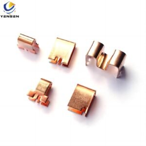
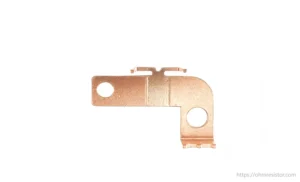
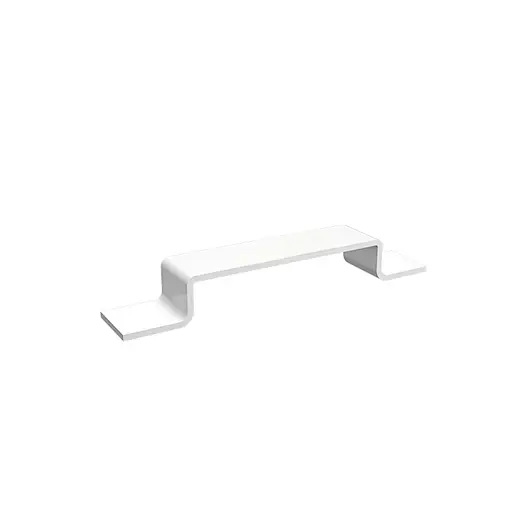
What’s a Through-Hole Jumper?
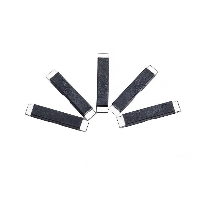
A Through-Hole Jumper is a pin, wire, or epoxy-coated leaded component that passes through the board and is soldered on the opposite side. Unlike SMT resistors, THT jumpers are bulkier and often used where mechanical strength is required.
Features of THT Jumpers:
Wire-like shape, often bent for fit.
Inserted through drilled holes.
Higher mechanical durability.
Easier to install by hand in prototypes.
Using Through-Hole Jumpers in PCB Design
Prototyping: Quick fixes when routing mistakes occur.
High-Current Paths: Provides stronger connection than SMT zero-ohm links.
Retrofit or Repair: Easy to solder on after PCB production.
Low-Cost Alternative: Useful in single-sided PCBs where routing is limited.
How Circuit Board Jumpers Function
Circuit board jumpers act as simple electrical bridges that either establish or alter a connection within a circuit. They are typically made from conductive materials, such as copper or tinned metal, and are applied when a designer needs flexibility or a quick modification. Depending on the application, jumpers may appear in several forms:
-
Soldered wire links – A fixed connection created by soldering a short piece of wire directly onto the PCB pads.
-
Plug-in or removable jumpers – Small, detachable connectors that allow engineers to easily open or close circuits during testing or configuration.
-
Designed PCB jump links – Narrow copper traces or pads on the board that can be cut, shorted, or bridged to change circuit behavior without redesigning the PCB.
By using these different jumper methods, manufacturers and engineers can fine-tune circuits, enable optional features, or provide easy repair and rework options.
Why Do You Use PCB Jumpers?
PCB jumpers are used to create or modify electrical connections on a printed circuit board (PCB). They allow designers to easily configure circuits, correct errors, or enable/disable features without redesigning the entire PCB. Jumpers can be temporary (for testing) or permanent (for final configurations).
| Reasons to Use PCB Jumpers | Description |
|---|---|
| Circuit Modification | Allows changing connections without redesigning the PCB. |
| Error Correction | Fixes mistakes in PCB layout after fabrication. |
| Feature Selection | Enables or disables specific functions in a circuit. |
| Testing & Prototyping | Provides temporary connections for testing and evaluation. |
| Flexible Design | Supports customizable or adjustable circuit configurations. |
Conclusion
In modern electronics, SMT PCB jumpers (zero-ohm resistors) dominate mass production due to automation and space-saving benefits, while THT jumpers still play a role in prototyping, high-power circuits, and manual repairs. By recognizing their appearance and application, engineers can make better design decisions and improve manufacturing efficiency.