Avoiding SMD Current Sense Resistor Issues in High Current Applications — A Real Case Study
SMD current sense resistor failure
In one of our recent projects, a customer was testing their PCB using SMD current sense resistors.The components had already been selected in their initial design before they reached out to us
On paper, the selection looked reasonable — the resistance value and power rating were both within range.
However, during testing, the results were not as expected.
This is actually quite common in high current designs. Many engineers start with resistance value and power rating, which makes sense — but real operating conditions often introduce additional factors that are easy to overlook.
What Happened in This Case
The customer had already selected and used SMD current sense resistors in their initial design before reaching out to us.
- 2 × 40mΩ / 3W SMD current sense resistors
- Mounted on a compact PCB
- Application: induction cooker circuit
During testing, they noticed something unusual:
One of the boards failed, and the resistor area temperature was already around 80–90°C.
At first, the assumption was simple:
maybe the resistor quality wasn’t stable.
But after looking deeper, that wasn’t the real issue
What We Found Behind the SMD Current Sense Resistor Failure
When we reviewed the application, a few things became clear.
The Heat Was Not Just from the Resistor
This is something easy to overlook.
The resistor itself wasn’t the only heat source.
- Nearby components were generating heat
- PCB layout was relatively compact
- Heat was accumulating in a small area
So even if the ambient temperature wasn’t extreme,
the local temperature around the resistor was already high
Power Rating Was Misunderstood
This comes up quite often.
The customer later asked:
“If the temperature reaches 90°C, can the resistor still handle 5W?”
In theory, a 5W resistor sounds sufficient.
But in practice, power rating is always linked to temperature.
Most resistors are rated at:
- 25°C or
- 70°C
Once you go above that, derating starts.
For example:
- At 90°C, a 5W resistor may only safely handle around 4W (or even less depending on conditions)
This part is not always obvious during initial design
In many cases, SMD current sense resistor failure is not caused by a single factor.
It is usually a combination of thermal conditions, PCB layout, and real operating load.
SMD Package Became the Limiting Factor
At this point, the key issue was no longer resistance or power.
It was the package.
SMD resistors are great for:
- Compact layouts
- Automated assembly
But they rely heavily on PCB copper for heat dissipation.
In this case:
- Limited copper area
- Limited airflow
- High surrounding temperature
Heat simply had nowhere to go.
What Changed the Situation
Instead of trying to push the SMD resistor further,
we suggested stepping back and rethinking the structure.
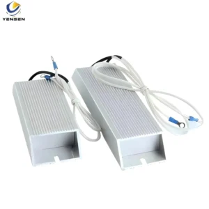
The customer eventually:
- Switched to a through-hole (shunt-type) resistor
- Adjusted the PCB layout
After that, the thermal situation improved significantly,
and the system became stable.
What This Case Reminds Us
This wasn’t a “wrong resistor” problem.
It was more about how the resistor behaves in a real system.
✔ Rated power is not the whole story
It only works under specific conditions.
✔ Local temperature matters more than ambient
What really counts is the temperature around the component, not just the environment.
✔ Package selection is critical in high current designs
In some cases, a larger or different structure (like through-hole)
can be much more reliable than a compact SMD solution.
A Small Thought
This kind of issue doesn’t usually show up in simulation or initial calculations.
It only becomes visible during real testing.
And by the time it fails, it often feels unexpected.
If you are working on:
- High current sensing
- Induction heating systems
- AI power or IGBT applications
and noticing things like:
- resistor overheating
- unstable readings
- failures during long-time operation
- it might be worth looking at the thermal path and package choice, not just the specs
- This is why SMD current sense resistor failure is often seen in high current designs, even when the initial calculations look correct
Closing
This case was actually quite typical.
Nothing was “wrong” at the beginning —
it just didn’t match the real operating conditions.
If you are facing similar issues in high current designs, it may be worth reviewing not just the resistor specification, but also the thermal path and package selection.
In many cases, a small structural change can make a significant difference in reliability.