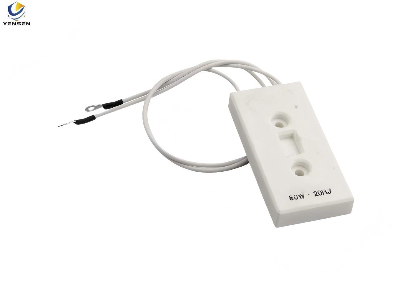
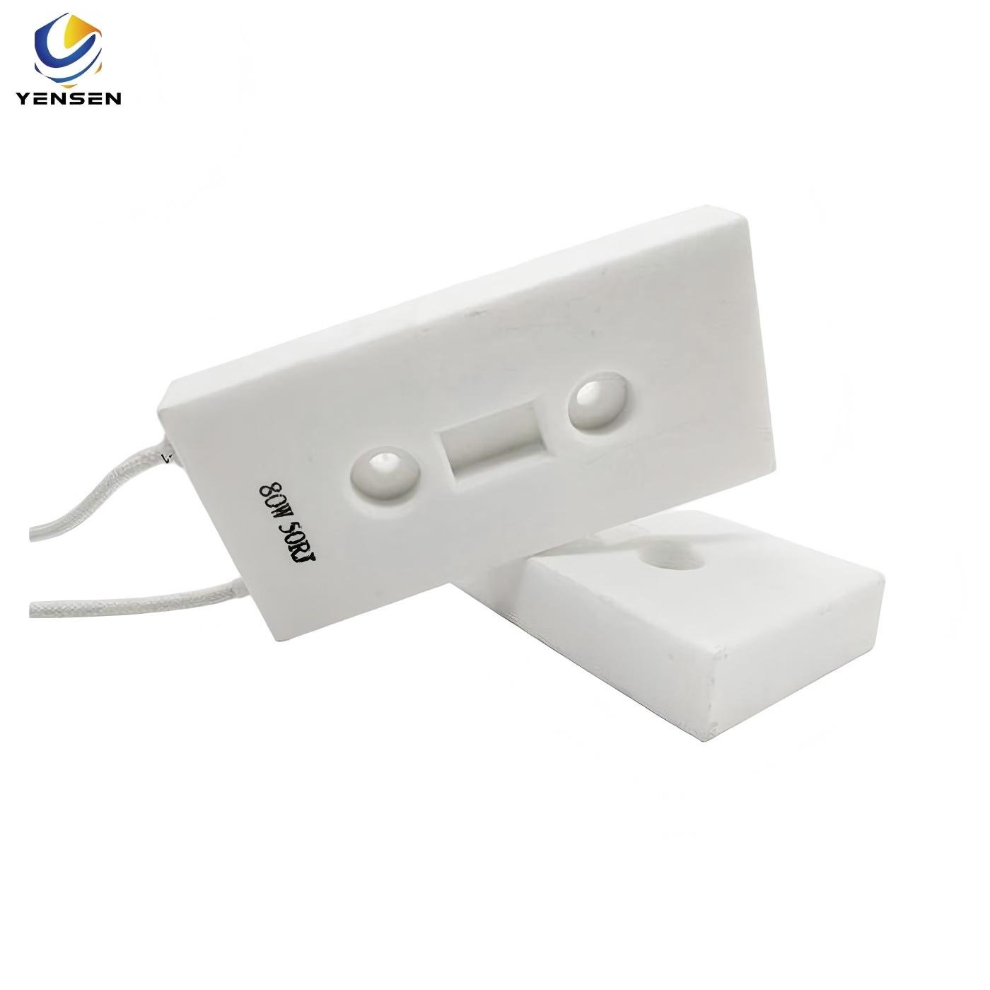
80W 20Ω High-Power Cement Resistor
Rated power range: 80W
Working voltage range: <1000V
Rated resistance range: 0.1Ω~10KΩ
Maximum withstand voltage: 1500V
Maximum accuracy: 1%
IP level: IP33
Vibration: 0.5g
Temperature drift range: ≤400ppm/℃
Working temperature range: -55℃~+275℃
Application areas: power supply system, charging equipment
Description
The 80W cement resistor is designed for soft start and surge protection in demanding circuits. Its non-inductive structure allows fast response and reduces EMI, making it ideal for power supplies, motor drives, and other industrial equipment.
With a ceramic core and cement coating, this resistor offers excellent heat resistance and flame protection, ensuring both safety and a long service life. In addition, its compact rectangular body simplifies installation and saves board space.
The 20Ω resistance value effectively limits inrush current and voltage spikes, improving the stability of your system. As a result, engineers can rely on this resistor for consistent performance, high reliability, and cost-efficient operation in industrial environments.
Key Features of 80W cement resistor
Rated Power: 80W
Resistance: 20Ω ±5%
Operating Temperature: -55°C to +200°C
Material: Ceramic core with cement coating
Non-inductive design: Ideal for high-frequency applications
Applications: Soft start, surge protection, inverter circuits, motor drives
Product Dimensions
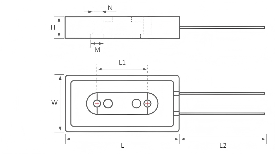
| Rated Power (W) | L±1 | L1±1 | L2±10 | W±0.5 | H±0.5 | M±0.2 | N±0.2 | Resistance Range (Ω) | Outlet Mode | Weight (g) |
|---|---|---|---|---|---|---|---|---|---|---|
| 60W | 90 | 35 | 200 | 45 | 15 | 10 | 5 | 0.1~10K | Lead Wire | 140 |
| 80W | 90 | 35 | 200 | 45 | 15 | 10 | 5 | 0.1~10K | Lead Wire | 140 |
| 100W | 90 | 35 | 200 | 45 | 15 | 10 | 5 | 0.1~10K | Lead Wire | 140 |
Electrical Characteristics
| Property | Test Method | Performance Requirements | Test Standard |
|---|---|---|---|
| Terminal Strength | 20N tensile load for 10 seconds | No visible damage | GB/T5729 4.16 |
| Vibration Resistance | Frequency 10Hz–500Hz, acceleration 10g | No visible damage | GB/T5729 4.22 |
| Short-time Overload | 10× rated power for 5 seconds | ΔR ≤ ±(2%R + 0.1Ω) | GB/T5729 4.13 |
| Insulation Resistance | 500V ±50V DC between leads and aluminum housing | ≥100MΩ | GB/T5729 4.6.1.3 |
| Dielectric Withstanding Voltage | 1000Vac, 5mA, 1 minute | No breakdown or flashover | GB/T5729 4.7 |
| Load Life | Rated power for 96h (1.5h ON / 0.5h OFF cycles at room temperature) | No visible damage | GB/T5729 4.25.2 |
| Damp Heat, Steady State | (40±2)℃, (93±3)%RH, 96 hours | ΔR ≤ ±(5%R + 0.1Ω) | GB/T5729 4.24.2.1.a |
| Rapid Temperature Change | -55℃ to +155℃, 5 cycles | ΔR ≤ ±(2%R + 0.1Ω) | GB/T5729 4.19 |
Resistor Usage Recommendations
When designing circuits, always leave a power margin of at least 1.5 times the calculated load.
For example, if the circuit voltage is 100 V and the current is 0.01 A, the power consumption is:
P = 100 × 0.01 = 1 W.
In this case, you should not select a 1 W resistor.
Instead, multiply the power by 1.5 to get 1.5 W.
Since 1.5 W resistors are uncommon, choose the next higher rating (2 W) to ensure safe and stable operation.
This margin helps prevent overheating and extends the resistor’s lifespan.
Typical Applications
Motor soft start circuits
Surge limiting in AC power lines
Power supply protection
Inverter drive circuits
Energy discharge in capacitor banks
Internal and External References
- Explore related products: fixed Resistors
- All products are manufactured using RoHS-compliant materials. For official regulatory information,
- see the EU RoHS Directive
Installation Tip
For best heat dissipation, mount the resistor on a metallic surface or attach a heat sink.
This method significantly improves thermal stability, reduces stress on the resistor, and extends its service life.